 |
||
| > Reader's Photo OX5 by Lockheed Martin |
||
 |
||
| • ADVERTISE WITH US | ||
| • WHO IS MOAB JEEPER? | ||
|

Home > Jeep Articles > Technical & Installation - Engine / Drivetrain > Rebuilding The 231: Assembly |
||||||||||||||||||||||||||||||||||||||||||||||||||||||||||||||||||||||||||||||||||||||||||||||||||||||||||||||||||||||||||||||||||
 |
||||||||||||||||||||||||||||||||||||||||||||||||||||||||||||||||||||||||||||||||||||||||||||||||||||||||||||||||||||||||||||||||||
|
Rebuilding The 231: AssemblyArticle written by text and photography by the J staffDate Added: 12/06/2007 Jeep?s popular transfer case goes under the wrench. |
|
In Standard Issue 6 of J Rations, we embarked on a two-part article detailing an in-depth rebuild of the widely employed NP 231 transfer case. That first installment outlined the complete disassembly of the 231. Now we bring it all back together with new bearings, seals, fork pads and a whole new outlook on life. While we are rebuilding this particular junkyard 231 to stock specs, this is an excellent opportunity to upgrade the 231 with a slip-yoke eliminator kit and shorter tailshaft (for lifted Jeeps). For that procedure, get a back issue of Standard Issue 2, wherein we installed the Tera Manufacturing/Novak Conversions Extreme Short Shaft Kit or search MOABJEEPER Magazine for articles about the Advance Adapters Heavy Duty SYE and Tom Wood?s SYE kits. Also, as a reminder, Crown Automotive?s Web site contains an exploded diagram of the 231, which is a good companion reference to this article. Now, off to the home stretch... SOURCE Crown Automotive Sales www.crownautomotive.net |
||||||
|
Installation | |||||||
|
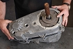
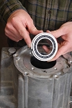
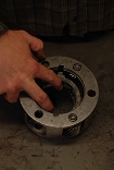
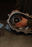
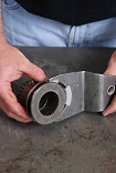
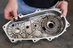
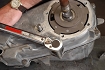
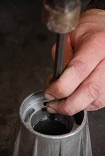
1. With the transfer case halves and all reusable components cleaned, the reassembly begins by installing the new front output shaft bearing into the front case. Get the bearing started into the bore as shown, then use a bearing installer or, as we did, a brass drift and hammer to evenly drive the bearing into the bore. When using a drift it can be difficult to get a bearing started. Keep at it and have patience. Once it?s going in evenly, make alternating taps around the bearing so it continues to go in straight. Lots of light precision taps are better than fewer heavy blows. This is delicate work. Continue tapping until the bearing is fully seated in against the retaining lip. You?ll know when it?s there by the sharp ring of the hammer and solid feel of the tap. |
||||||
|
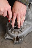
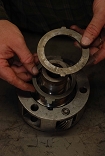
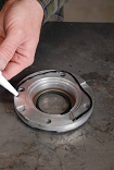
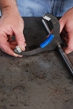
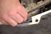
2. Reinstall the snap ring by squeezing it together, inserting it into the bore, then walking the ring down the bore and into its groove with a flathead screwdriver. |
||||||
|
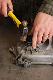
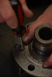
3. You?re now ready to install the new front output shaft seal. Seals are mighty tricky to install without a seal installer. When using a hammer, it?s similar to starting a bearing into a bore but often more frustrating, as seals tend to wobble when you strike them. In addition, the metal component of the seals are easily damaged. It takes deliberate, ?square-on? blows to seat them without damage. Again, patience and careful tapping will do the trick. Carefully hammer the seal into the bore until it is fully seated. |
||||||
|
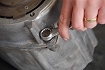
4. Our new input gear bearing from Crown Automotive came with its snap ring already installed. If yours does not, install the snap ring onto the bearing as shown. |
||||||
|
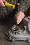
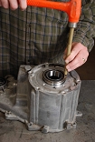
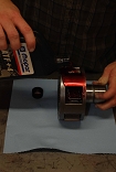
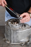
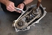
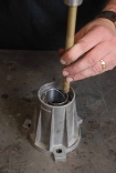
5. Use a press or, as shown here, a hammer and brass drift to install the input gear bearing into the front of the case until the snap ring seats against the case. Again, carefully walk the bearing into the bore with carefully placed taps around the circumference of the bearing. |
||||||
|
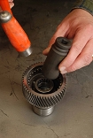
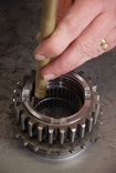
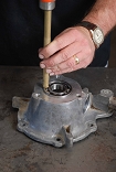
6. Installing the new mainshaft pilot bearing into the input gear is best done by using a press. Lacking this tool, you?ll need to get creative. We placed the bearing into the gear and set a sturdy socket with the same diameter as the bearing onto the bearing. The socket provided the tapping surface, and because it is the same diameter as the bearing, kept the bearing from wobbling as we applied the initial blows. |
||||||
|
7. Once started into the bore, use a brass drift and hammer to finish seating the bearing. Be careful that you don?t let the drift slip and damage any of the needle bearings or the cage. |
||||||
|
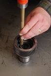
8. Moving to the low-range gear, install the first thrust washer into the gear assembly as shown. |
||||||

|
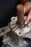
9. Install the input gear allowing the gear teeth to mesh with the planetary gears. |
||||||
|
10. Now install the second thrust washer and the retainer. |
||||||
|
11. With the gear, thrust washers and retainer properly installed in the low-range gear, secure the assembly with the snap ring. |
||||||
|
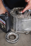
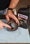
12. Give the input gear a shot of automatic transmission fluid and spin the gear set to lubricate the cogs. Next, spread some lube around the input gear where it goes into the front bearing. |
||||||
|
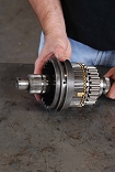
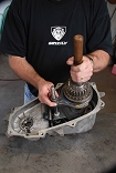
13. Start the input and low-range gear assembly into the front case as shown. |
||||||
|
14. If you use a press to install the gear assembly into the front bearing make sure not to press on the low range gear case, as this may damage the gear case and thrust washers. Also, do not press on the input gear pilot bearing, as it may push the bearing too far into the gear bore. We tapped the assembly into the front bearing using a brass drift and hammer, tapping along this ledge in the input gear. When the gear assembly is properly seated the input gear snap ring groove will be fully exposed on the front side of the case. |
||||||
|
15. Install the input gear snap ring onto the gear to secure the assembly. |
||||||
|
16. Install the new oil seal in the front bearing retainer. |
||||||
|
17. Flip the retainer over and apply a 1/8-inch bead of RTV silicone around the mating surface of the retainer as shown. Let the silicone skin-over (see manufacturer?s recommendation for time) before installing onto the front case. |
||||||
|
18. Apply a light coat of automatic transmission fluid (ATF) around the end of the input gear and rubber seal. This is good practice any time you are installing a seal. Never install a dry seal. |
||||||
|
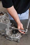
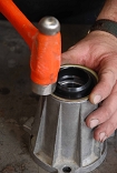
19. Install the bearing retainer onto the case and torque the bolts to 16 ft. lbs. |
||||||
|
20. Install the sector shaft O-ring, followed by the plastic bushing, into the sector shaft bore. |
||||||
|
21. Reinstall the shift sector in the front case. |
||||||
|
22. From outside the case, reinstall the range lever and attaching nut onto the end of the shift sector and torque to 22 ft. lbs. |
||||||
|
23. Insert the detent plunger, spring, O-ring and plug, in that order, into the shift sector detent bore. |
||||||
|
24. Crown Automotives 231 master rebuild kit comes with new fork pads for the range fork and mode fork. Remove the old pads from the range fork and install the new ones. |
||||||
|
25. Slip the range fork onto the shift hub as shown. |
||||||
|
26. Drop the range fork/shift hub assembly into the case, making sure the range fork pin fits into the sector slot. |
||||||
|
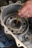
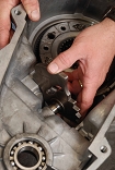
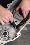
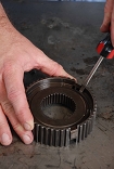
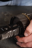
27. When we first disassembled our 231 we decided not the replace the drive sprocket bearings (there are two sets) because the bearings were in perfect shape. Upon closer examination we noticed that the rear bearing (seen here on top) was seated too far into the sprocket bore and was out of spec. Having the two replacement bearings on hand, we decided to go ahead and replace them. Both bearings must be pressed or hammered out at the same time. We used a brass drift and hammer to do the deed. |
||||||

|
28. Reinstallation of the replacement bearings is done in a specific order. First install the front bearing until it is flush with edge of the sprocket bore. Again, a brass drift is used. |
||||||
|
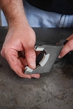
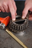
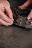
29. Turn the sprocket over and install the rear bearing. The rear bearing seats into the sprocket bore 4.6mm (11/64 inches) below the edge of the bore. We used a feeler gauge set, added up the gauges until we hit the magic number, then gently tapped the bearing into place until reaching the desired depth. |
||||||
|
30. With the drive sprocket bearings installed, lubricate the bearings with ATF. |
||||||
|
31. If you disassembled your synchro hub, reassemble at this time. As you will see, the synchro hub assembly is secured by two springs on either side and three struts. They?re simple to take apart, clean and put back together, so we recommend doing so before reassembly. |
||||||

|
32. If you?ve not already lubricated the drive sprocket bearings with ATF, do so now, along with the brass stop ring and synchro hub. Install the drive sprocket onto the mainshaft as shown... |
||||||
|
33. ...followed by the stop ring... |
||||||
|
34. ...and synchro hub. The synchro hub struts seat on the stop ring lugs. |
||||||
|
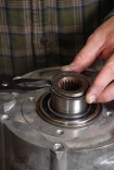
35. Using ring pliers, reinstall the synchro snap ring around the mainshaft to secure the drive sprocket, stop ring and synchro hub to the mainshaft. |
||||||
|
36. Install the synchro sleeve onto the synchro as shown. The beveled splined ends of the sleeve must face the stop ring. |
||||||
|
37. Install the new pads onto the mode fork. |
||||||
|
38. Slip the mode fork/shift rail assembly onto the synchro sleeve in the orientation seen here. |
||||||
|
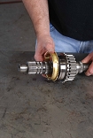
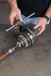
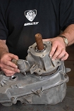
39. The mainshaft/mode fork assembly can now be installed into the front case. The end of the mainshaft will slip through the shift hub while the shift rail will go through both range fork bushings. The only tricky part here is making sure the range fork pin doesn?t come out of the sector slot during assembly. |
||||||
|
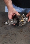
40. Place the drive chain on the output shaft and lower into the case as shown. It may take some creative jostling to get the chain wrapped around the mainshaft cogs (you may have to lift the mainshaft slightly to gain some maneuvering room), but eventually it comes together. If installing a new chain (which is tighter), the output shaft and chain may need to be attached to the mainshaft and the output shaft, chain and mainshaft dropped into the case as an assembly. |
||||||

|
41. Reinstall the mode spring onto the shift rail. |
||||||
|
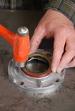
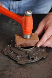
42. Install the new oil seal onto the oil pump. This is a rather wide seal, and wider seals are often more challenging to install than those of a smaller diameter. On seals like this, one trick to getting them started evenly is to lay a piece of hardwood over the seal and apply a solid (but not overly aggressive) blow to the center of the wood. Done right, this will start the seal into the bore so you can finish the seating with a brass drift. |
||||||
|
43. Reinstall the oil pump O-ring in the pickup tube bore. Clean the pickup tube and filter with brake cleaner. If you install the spray straw into the nozzle of the brake cleaner can you can dissolve and shoot out any built-up gunk in the filter mesh. |
||||||
|
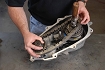
44. Reinstall the pickup tube/filter assembly into the oil pump. The pump lays against the outside of the rear case while the pickup tube and filter seats into the case as shown (there?s a retaining slot in the case to accommodate the filter. The pump will be secured by the rear retainer when it is installed onto the rear case. |
||||||
|
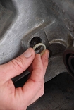
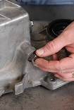
45. Clean and reinstall the magnet into its slot in the front case. |
||||||
|
46. Apply a 1/8-inch bead of RTV silicone to the perimeter of the front case and let skin per the manufacturer?s recommendations. |
||||||

|
47. Install the rear case onto the front case. You?ll need to make sure the two locating dowels are in place. Also, the oil pump?s inner gear should spline to the mainshaft. The mainshaft splines tend to drop below the oil pump gear, so pull up on the mainshaft to engage if necessary. |
||||||
|
48. The two locating dowels are the only two case bolts which use washers. |
||||||
|
49. Torque all front-to-rear case bolts to 30 ft. lbs. |
||||||
|
50. Moving to the rear retainer, install the new bearing. |
||||||
|
51. Apply RTV silicone to the rear retainer and install over the mainshaft and onto the rear case. Ours took a little rubber-mallet-persuasion to fully seat onto the case. Torque the retaining bolts to 18 ft. lbs. |
||||||
|
52. While pulling upward on the mainshaft, install the rear bearing snap ring. |
||||||
|
53. It?s a good idea to replace the extension housing bushing (particularly since one is supplied with the master rebuild kit), but it?s a bit challenging to remove the old one. We found success by using a steel punch to knock it out of the bore. It?s messy, but it works. |
||||||
|
54. Tap the new bushing into the bore with a brass drift... |
||||||
|
55. ...then install the new oil seal. |
||||||
|
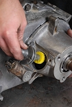
56. Drop in the speedometer adapter and pinion assembly, ensuring the pinion meshes with the mainshaft splines, and secure with the adapter clamp. |
||||||
|
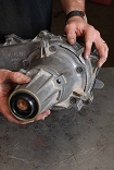
57. Apply RTV silicone to the mounting surface of the extension housing and torque to 30 lb. ft. Install the front yoke and replacement seal washer and nut (110 ft. lbs.), drain plug (35 ft. lbs.), vacuum switch (35 ft. lbs.) and your 231 rebuild is complete. Once installed in the vehicle, fill with Mopar ATF Plus or Dexron II ATF and secure the fill plug to 35 ft. lbs. |
||||||
Purchase / Vendor Info
|
| Vendor Name: | Crown Automotive Sales Co Inc |
| Address: | 230 Turnpike St Canton, MA 02021-2359 |
| Website: | http://www.crownautomotive.net/ |
 Our
Thank You's!
Our
Thank You's!
MOABJEEPER Magazine would like to thank the JRations staff for taking the time to do a step-by-step rebuild of the NP231. It is surely going to be helpful for anyone attempting this rebuild themselves.
